Non-contact Tank Liquid Water Level Sensor


Welcome to Weather-Above
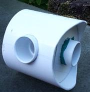
(fig 1a) White plastic is cut to fit the shape of the outer shield, cut out hole to take the bottom of the air intake 90° bend
(fig 2a) Air intake 90° angle with supporting ring, and the outer air intake shield
(fig 3a) Air intake 90° angle with supporting ring, and the outer air intake shield
(fig 4a) Fully assembled air intake with solar shield, air intake filter to keep out little bugs
fig 1a
fig 3a
fig 2a
fig 4a
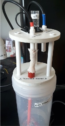
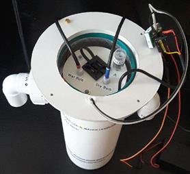
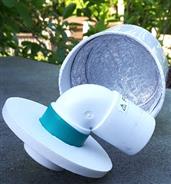
(Fig b1) Sensor mounting holder and distilled water container 400 ml. To make the holder I used 2 plastic discs which have three supporting legs ,connecting to the bottom ring . One of the supporting legs go straight through into the distilled water container. In the image you can just make out the clear plastic water fill cup this contains a small filter to stop any debris entering into the water container. Two temperature sensors are mounted on the top indicated by the colour blue for the dry bulb and red for the wet bulb. The wet bulb temperature sensor as a cotton sock, this can be made from a white natural cotton shoelace. What ever material you use for the wet bulb always boil the material to eliminate any oil grease residues. In the image you can see a red plastic tube in the distilled water container, this contains a very absorbent core feeding distilled water to the white cotton Wick. (fig b2) On top of the mounting disc to enable easy removal from the solar radiation shield is a black cable tie clip loop.
fig B1
(fig b2)
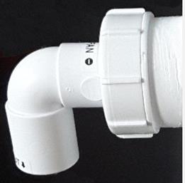
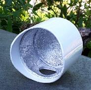
(fig b3) This image consist of the fan housing with the air outlet ,this is made by using two plastic plumbing fittings, a standard 90° overflow bend . Second component is a screwed lid pipe blanking end (fig b4) a hole has been drilled into the screw lid to accommodate the 90° angle, in the larger area behind the screw lid as a small 12 V fan which will pull air across the temperature sensors (fig b5)
(fig b3)
(fig b4)
(fig b5)
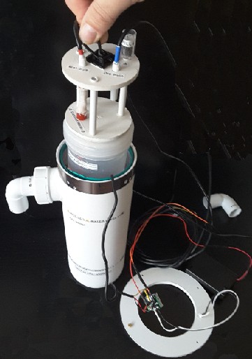
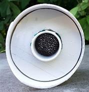
(fig C1) Outside red led (Low water indication maintenance needed)
C1
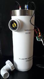
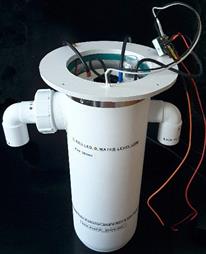
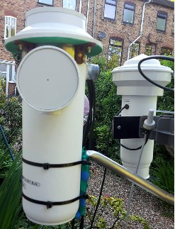
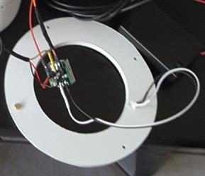
The outside container is the same specification as used for the solar radiation screen for my outdoor temperature and humidity sensors. On the inside of the container wall is a double aluminium foil sandwiched between a thin foam insulation material,this makes an excellent user-friendly solar radiation membrane . Top mounting flange cut out of plastic this is for fixing the plastic top radiation shiel it consists of multiple layers of solar radiation membrane and air gaps, the top is sealed on top of the ring, the ring is fixed to brackets underneath in the side of the outer plastic wall, four screws enable the whole top to be removed for filling up distilled water reservoir and other maintenance.
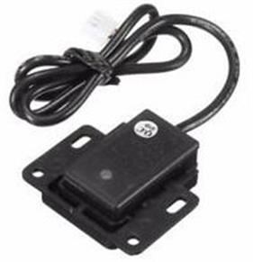
Non-contact liquid water level sensor is clipped on to the water reservoir tub when the water level drops to 150 mL red warning light is activated indicating maintenance is required . by unscrewing four screws from the top of the solar radiation shield you then simply add 300 mL of distilled water to the filling cup.
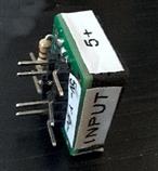
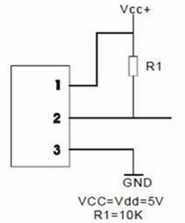
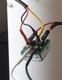
The wet bulb and dry bulb sensors and the distilled water reservoir are enclosed in a solar radiation screen so it's important to have a way of knowing when the distilled water drops to a level giving a warning light to indicate maintenance is required, this is where the non-contact with liquid level sensor comes into its own .I am using a pull-up resistor connected to a red LED which is connected to a 5 V DC supply. I made a small printed circuit board with the pull-up resistor and output pins to connect a 5 V supply, LED connections coming off the pull-up resistor and on the back of the printed circuit board there is a moisture resistant coating, the small module is mounted in the top of the solar radiation screen which is well away from any of the sensors.
PCB
connector module
Aspirated solar radiation screen for wet and dry bulb sensors
Designed by Michael G Parry-Thomas
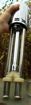
To calibrate the one wire wet and dry bulb. I used an Aspirated Psychrometer (Wet & Dry Bulb Hygrometer) by Casella of London. This device consists of a clockwork fan, when fully wound it will keep running for seven minutes, it's very well-designed and is perfect for calibrating purposes. Inside the device consists of two accurate thermometers consisting of mercury one of the thermometers as a wet work attached to it, when the key on top of the advice is wound fully air is drawn through the bottom of the tubes giving a constant airflow and allowing to take a accurate wet and dry bulb reading this is what I've used to calibrate my humidity sensors and wet and dry bulb project sensors