

Welcome to Weather-Above
UV1 project consists of a Oregon UVR 138 {Ultra Violet sensor) and a extra temperature sensor THC238 with a probe
Converting a UV sensor for weather station Oregon Scientific Wireless Model WMR928NX
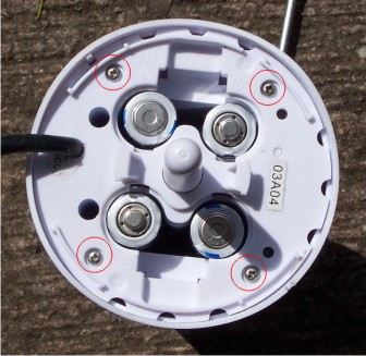
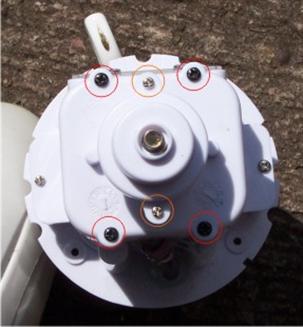
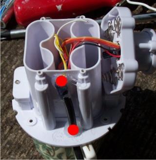
Fig 1
Fig 2
Fig 3
1st Remove the four screws marked in red
located at the bottom of the UV sensor near battery compartment
2nd the outer cover will now be loose
pull the centre protruding plastic to separate the case
indicated in figure 1 Green Square
3rd remove the four screens first marked in red
then remove the two screws holding the sensor top indicated by Orange dots

When you remove the outer casing be careful not to lose
the rubber Gromit this may still be positioned inside the plastic
or located in the UV photodiode top
this is important on reassembly, make sure this Gromit is in place
Drill two holes indicated in figure 3
Be careful when you drill you do not damage any of the wires
on the other side of the casing
I recommend using a screened cable it is important to measure out
exactly 27 inches
Thread the cable through the bottom and through the second hole strip away
enough of the casing so there is plenty wire coming through to the top of the
sensor
I've used hot melt glue around the two holes to keep the cable in place
Please make a donation if you use this information the converting UV sensor
I appreciate it if you would sign my guestbook
Designed by M Parry-Thomas
Second stage
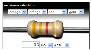
You need to cut-off the probe from your extra temperature sensor strip back the outer casing you're going to need a resistor
Then solder one wire from your extra temperature sensor to one end of the resistor
Please see Fig 6
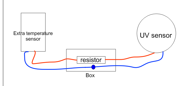
Then you are left to solder one wire from the extra temperature sensor to the other wire from your UV sensor
The best way to seal everything is use a small box melt some hot melt glue into the bottom of the box
then position the resistor in the middle and position the other wire you are connected alongside
and fill the remainder with hot melt glue so you have a solid block
Copyright 2008
Fig 4
Fig 6
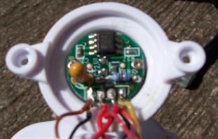
Fig 5
You need to solder 2 wires in place
indicated by the red dots in Fig 5
Please note there are other wires
soldered to the circuit board
you need to keep them exactly in the same place
all you are doing is adding 1 wire to the indication
Markings in red
When you have soldered the 2 wires in place reassemble your uv sensor
